
Introduction
Physical Overview
Operational Views
Design Goals
- Guest and Operator Safety
- High Reliability and Availability (the number of people going through the ride everyday is very large and lines get long).
- Low Development and Repair Cost—use "off the shelf" components whenever possible.
Nancy's Shuttle is an entertaining, educational ride through the universe of safety. Guests board shuttle-themed vehicles from a Station Area themed as a space station, and depart for a low speed ride through various vistas designed to expose the rider to concepts of software and systems safety. The Show Area consists of three-dimensional sets recreating scenes of nuclear generators, airport control towers, bio-imaging systems, and other instances where software plays an integral role in system safety.
The attraction is capable of supporting a rider capacity of 1400 guests per hour, with the guest experience lasting approximately four minutes including unloading and loading operations. Each vehicle can accommodate up to seven guests, and will travel at a constant speed (approximately 3 feet per second) throughout the attraction.
Load Operators dressed as flight technicians will assist in the shuttle load / unload process. Guests will be escorted into queue lines, one for each of the three rows of seats in the vehicle. A gate will automatically open when a shuttle arrives in the load area. When guests are properly seated in the shuttle, the Load Operator will close the gate and initiate shuttle motion. Once the shuttle is launched, it proceeds without the need of operator intervention until it returns to the station and automatically stops for unloading. When guests have exited, the Load Operator will advance the shuttle to the load area for the next group of guests.
Under Load Operator control, shuttles can be added from a maintenance area or removed from the attraction by means of a pair of track switches located just downstream of the station where guests load and unload.
This document describes the role of automation in a new ride called "Nancy's Shuttle" to be constructed at the Safeware Theme Park. It contains information for engineering staff and other stakeholders needed to perform a preliminary evaluation of the feasibility, safety and maintainability of the subsystems involved in the automation of this ride.
As shown in Figure 1, the ride site consists of three main areas: The Show Area, Station Area and Maintenance Area.
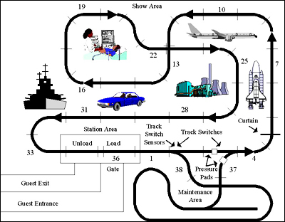
Figure 1 - Physical Layout. (Image courtesy of Nancy Leveson.)
Vehicles may be added from the Maintenance Area, or removed from active use into the Maintenance Area by means of a pair of track switches located just downstream of the Station Area. Each track switch has two lockable positions, "main" and "maintenance in". During normal operation, both track switches will be in the "main" position. When the first track switch is set to the "maintenance in" position, the vehicle will be steered into the maintenance area. Setting the second track switch to the "maintenance in" position will steer a vehicle exiting the maintenance area back onto the main rail. The track switches are normally moved by the Load Operator using the Maintenance In selector switch on the Load Operator's Console. Either track switch may be moved independently by a maintenance operator using a mechanical crank. This allows vehicles to be moved by a self-powered towing vehicle into and out of the maintenance area when the segmented bus-bar is not energized.
When the Load Operator changes the position of the Maintenance-In selector switch on the Load Operator's Console, the track switch locking pins will be released, the appropriate track switch direction will be signaled and the track switch motor will be engaged. The motor movement must stop as soon as the track switch reaches the desired position to prevent damage to the track switch or damage to the motor. To complete the operation, the track switch locking pins must be locked.
While in the Show Area, each vehicle will pass through vistas on System Safety in the Space Exploration, Commercial Aviation, Medical Technology, Energy and Automotive Systems sectors. The length of the path in the Show Area is 594 feet.
At the entrance to the first vista, there is a computer-controlled sheet metal curtain that is raised to allow a vehicle to enter a darkened tunnel. This curtain blocks daylight from this first vista in the Show Area to allow for projection of a short video sequence. A hydraulic pump is used to raise the curtain.
The Station Area is divided into two zones: The Unloading Zone and the Loading Zone. It is possible to unload a vehicle while the previous unloaded vehicle is being loaded with guests. There is a gate at the entrance to the Station Area that prevents guests from entering the Loading Zone except during the vehicle loading process.
Each vehicle follows a path determined by a guide rail. There is a guide beneath each vehicle that latches onto the rail. There is a segmental bus-bar beside the guide rail that supplies electrical power to the vehicle through an electrical contact attached to the bottom of the vehicle. The vehicle rides on an elevated surface approximately 5 feet above ground level. (Because of seasonal flooding at the theme park, the track surface has been elevated to avoid electrical hazard that might otherwise occur if the energized bus-bar were immersed in water.) The width of each vehicle and the elevated surface is approximately 6 feet and 7 feet respectively.
Each segment of the bus-bar supplies each vehicle with 120v single-phase power. The vehicle will achieve a constant speed of approximately 3 feet per second within 4 seconds of energizing the bus-bar. It will come to a complete rest within 3 seconds when the bus-bar is de-energized.
In the Show Area, the approximate length of each segment of the bus-bar is 18 feet. There are a total of 33 segments in the Show Area, numbered 1 through 33. There is one intersection in the Show Area at the boundary between Segments 12 and 13 and at the boundary between Segments 22 and 23, e.g., a vehicle entering the intersection from Segment 12 will exit the intersection into Segment 13. There are three segments in the Station Area and two segments in the Maintenance Area. Each vehicle is unloaded and loaded while at rest in Segments 34 and 36 respectively. Segment 35 is a short-length buffer zone between the Unloading and Loading zones. Segment 37 is energized when a vehicle is being moved from the Maintenance Area into the Show Area. Segment 38 is energized when a vehicle is being moved from the Show Area into the Maintenance Area. Except for Segments 37 and 38, vehicles are moved in the Maintenance Area by a self-powered utility vehicle. The vehicles are also light enough to be pushed or pulled by the maintenance Load Operators without machine assistance.
All of the ride controls are housed in a glass-sided booth located in the Station Area. Within this booth, the Load Operator has an unobstructed view of the entire Station Area and the initial portion of the Show Area (up to the curtain just before the first vista).
When the ride is operational, the Load Operator assists passengers during unloading and loading operations, as well as controls the dispatching of vehicles into the Show Area. The Load Operator is also responsible for moving vehicles into and out of the Maintenance Area. The Load Operator is also trained to respond to emergencies and other unusual situations.
There is a Main Power Reset Button mounted on one side wall of the booth and a Main Power On / Off Switch mounted the opposite side wall. The Load Operator's Load / Unload Console is mounted at waist level in front of the Load Operator (as the Load Operator stands in the booth facing the Loading Zone).
3.1 Normal Steady State Operation
When operating at maximum capacity, a vehicle may be unloaded in the Unloading Zone at the same time that the previously unloaded is being loaded with guests in the Loading Zone. After closing the gate, the Load Operator visually check that all guests in the Station Area are safely seated in the vehicle in the Loading Vehicle. The Load Operator then presses the "Load Advance" button on the Load Operator's Console. This action causes the vehicle in the Loading Zone to be dispatched to the Show Area and the vehicle in the Unloading Zone to be advanced into the Loading Zone. A vehicle is allowed to enter the Unloading Zone from the Show Area whenever the Unloading Zone is empty. The gate at the Station Area entrance will open automatically whenever a vehicle arrives in the Loading Zone. When operating at maximum capacity, a vehicle will be dispatched from the Station Area into the Show Area once every 18 seconds on average.
At any time, the Load Operator may inhibit the movement of the vehicle in the Loading Zone by pressing the Dispatch Inhibit button. Once pressed, vehicle movement in the Loading Zone will be inhibited until this push / pull button is pulled. While in this state, vehicles may still enter the Unloading Zone.
The ride may be operated below maximum capacity by shunting one or more vehicles to the Maintenance Area and dispatching vehicles less frequently in response to operational needs.
3.2 Removing and Adding Vehicles
A vehicle at rest in the Loading Zone may be removed from active use by means of the track switches. Prior to pressing the Load Advance button, the Load Operator must select the "In" position of the Maintenance In selector switch on the Load Operator's Console. After closing the gate and then pressing the Load Advance button, the vehicle will move into the Maintenance Area.
To add a vehicle from the Maintenance Area, the vehicle must be moved by the Maintenance Load Operator onto Segment 37. Prior to pressing the Load Advance button, the Load Operator must select the "In" position of the Maintenance In selector switch on the Load Operator's Console. After closing the gate and then pressing the Load Advance button, the vehicle will from the Maintenance Area into the Show Area.
The main goals for the design of this system are: